The Core of Precision Motion: A Deep Dive into the Servo Drive Working Principle
In the world of industrial automation, precision is not
just a desire; it's a requirement. From the intricate assembly of electronic
components to the high-speed packaging of consumer goods, the ability to
control movement with exceptional accuracy is paramount. At the heart of this
capability lies a critical component: the servo drive. Often called an
amplifier or motion controller, the servo drive is the intelligent intermediary
that translates a low-power command signal into high-power motion. To truly
appreciate the engineering behind modern automation, one must first understand
the fundamental servo
drive working principle.
This article
will demystify the inner workings of servo drives, explaining the core
concepts, the components involved, and how they collaborate to achieve precise
control over position, velocity, and torque.
Explore Our Servo Drive at Ekra Cargo
What is a Servo System?
Before isolating
the drive itself, it's helpful to see it in context. A servo system is a
closed-loop system comprised of three primary components:
1. Controller: This is the "brain" that generates the
command signal. It dictates the desired position, speed, or torque based on a
pre-programmed task.
2. Servo Drive: Acting as the "brawn,"
the drive receives the command from the controller and powerfully amplifies it
to provide the necessary electrical energy to the motor.
3. Servo Motor: This is the "muscle"
that converts the electrical energy from the drive into precise mechanical
movement.
The system is
"closed-loop" because it constantly checks its own performance. A
feedback device, typically an encoder or resolver attached to the motor, sends
real-time data about the motor's actual position and speed back to the drive.
The drive then compares this actual data to the command signal from the
controller and makes instantaneous corrections. This continuous feedback loop
is what allows for such high levels of accuracy and stability.

The Step-by-Step Servo Drive Working Principle
The servo drive working principle can be broken down into a
continuous cycle of command, amplification, action, and correction. Let's
explore this process step by step.
Step 1: Receiving the Command Signal
The process
begins when the servo drive receives a low-voltage command signal from the main
system controller (e.g., a PLC or CNC controller). This signal specifies the
target parameters for the motion profile, such as:
·
Position Command: "Move to exactly 1,000 encoder counts."
·
Velocity Command: "Rotate at a constant speed of 3,000 RPM."
·
Torque Command: "Apply 5 Nm of force."
Step 2: Interpreting and Processing
The drive's
internal processor interprets this command signal. In advanced drives, this
stage involves complex trajectory planning, ensuring movements are smooth and
not jerky, which could cause mechanical wear or product damage.
Step 3: Amplifying the Power
This is a core
function of the drive. The command signal is weak and cannot power a motor. The
drive draws high-voltage, high-current AC power from the mains supply (e.g.,
240VAC or 480VAC) and uses a technology called Pulse Width Modulation (PWM) to
create a powerful, synthesized AC output for the motor.
In PWM, the
drive switches the power supply on and off at a very high frequency. By varying
the width of these "on" pulses, it effectively controls the average
voltage and current delivered to the motor windings, thus controlling its speed
and torque.
Step 4: Driving the Motor
The amplified
power from the drive is sent to the servo motor's stator windings. This
generates a rotating magnetic field that drags the motor's rotor along with it,
creating precise mechanical rotation.
Step 5: Gathering Feedback
While the motor
is turning, the feedback device (encoder) mounted on the motor shaft constantly
monitors its actual position and speed. This real-time data is sent back to the
servo drive without delay.
Step 6: Calculating Error and Correcting
This is the
critical "closed-loop" step. The drive's processor compares the
feedback (the motor's actual position/speed) with the
original command signal (the desired position/speed). The
difference between these two values is called the "error."
If there is any
error—for instance, the motor is lagging slightly behind where it should be—the
drive immediately adjusts its output power. It increases the voltage and
current to the motor to make it catch up. Conversely, if the motor is going too
fast, the drive reduces power. This correction happens thousands of times per
second, ensuring the motor follows the commanded path with extreme accuracy.
This entire
cycle—Command → Amplify → Act → Feedback → Correct—repeats continuously for the
duration of the motion task, creating a dynamic and highly responsive system.
Key Control Loops Within the Principle
A modern servo
drive typically manages three nested control loops simultaneously:
1. The Inner Loop: Current/Torque Control: This is the fastest loop. It
regulates the amount of current flowing to the motor, which directly controls
the torque produced. Precise torque control is essential for applications
requiring consistent force, like pressing or winding.
2. The Middle Loop: Velocity Control: This loop uses feedback to ensure
the motor maintains the commanded speed, even under varying loads. It takes the
error between commanded and actual speed and adjusts the torque command to
compensate.
3. The Outer Loop: Position Control: This is the slowest but most
overarching loop. It ensures the motor arrives at the exact position commanded.
It processes the position error and generates the required velocity command to
eliminate that error.
The Indispensable Role of the Servo Drive
Understanding
the servo drive working principle makes it clear why this component is
indispensable. It is not merely a power switch; it is an intelligent motion
controller that provides:
·
High Precision and Accuracy: The closed-loop system eliminates
drift and corrects errors in real-time.
·
Rapid Acceleration and Deceleration: Drives can provide high burst of
current for fast starts and stops.
·
High Torque at Low Speeds: Unlike standard motors, servo
motors maintain full torque even at very low rotational speeds.
·
Resonance Suppression: Advanced drives can detect and filter out
mechanical vibrations, preventing damage and instability.
·
System Protection: They monitor for overloads, over-temperature, and short
circuits, protecting both the motor and the machinery.
Choosing the Right Drive for Your Application
The
effectiveness of a motion control system hinges on selecting a high-performance
servo drive that perfectly executes the principles described above. The drive
must be robust, precise, and capable of communicating seamlessly with your
controller.
For engineers
seeking a component that embodies the highest standards of the servo drive
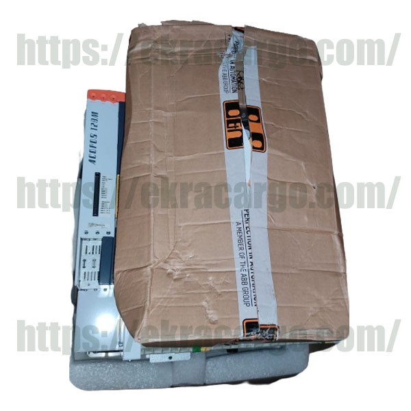
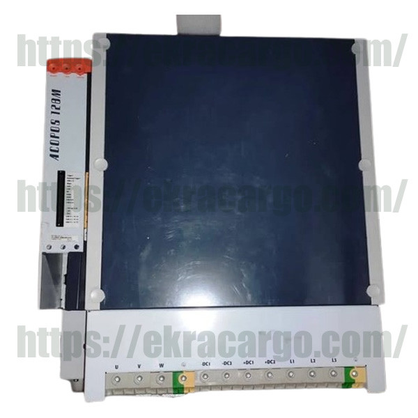
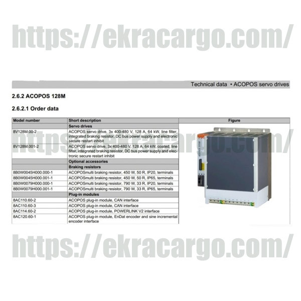
working principle, the BR
ACOPOS 128M Servo Drive 8V128M00-2 (98kVA) represents a top-tier
solution. This drive is engineered for demanding applications, offering
exceptional dynamic response, precise control, and advanced features that
ensure optimal performance in complex automation tasks. By integrating such a
capable drive, you are ensuring that the core of your motion system operates
with maximum efficiency and reliability.
Conclusion
The servo drive working principle is a brilliant application of closed-loop control theory. By continuously comparing a desired command to actual performance and making instantaneous corrections, the servo drive transforms a simple electric motor into a tool of unparalleled precision. It is the key enabler for the speed, accuracy, and flexibility that define modern industrial automation. From robotics to CNC machining, the sophisticated dance of command, power, and feedback orchestrated by the servo drive continues to push the boundaries of what is possible in mechanical engineering and manufacturing.

Ekracargo.com - Your trusted partner in industrial efficiency, providing a wide range of premium quality spare parts at competitive prices.
Contact Info
- Address: House 54 | Road 14 | Sector 14 | Uttara | Dhaka 1230 | Bangladesh
- Phone: Contact: +8801634736139,+8801789394669 (WhatsApp)
- Email: info@ekracargo.com